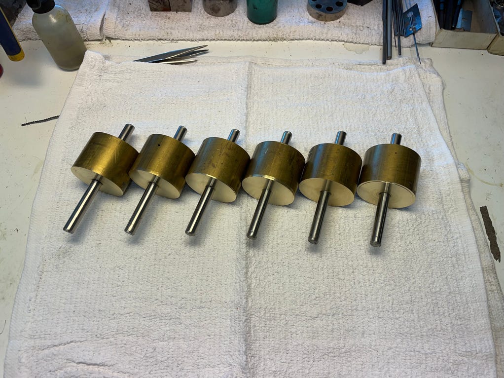
I always make several to save time and have extras for other projects.
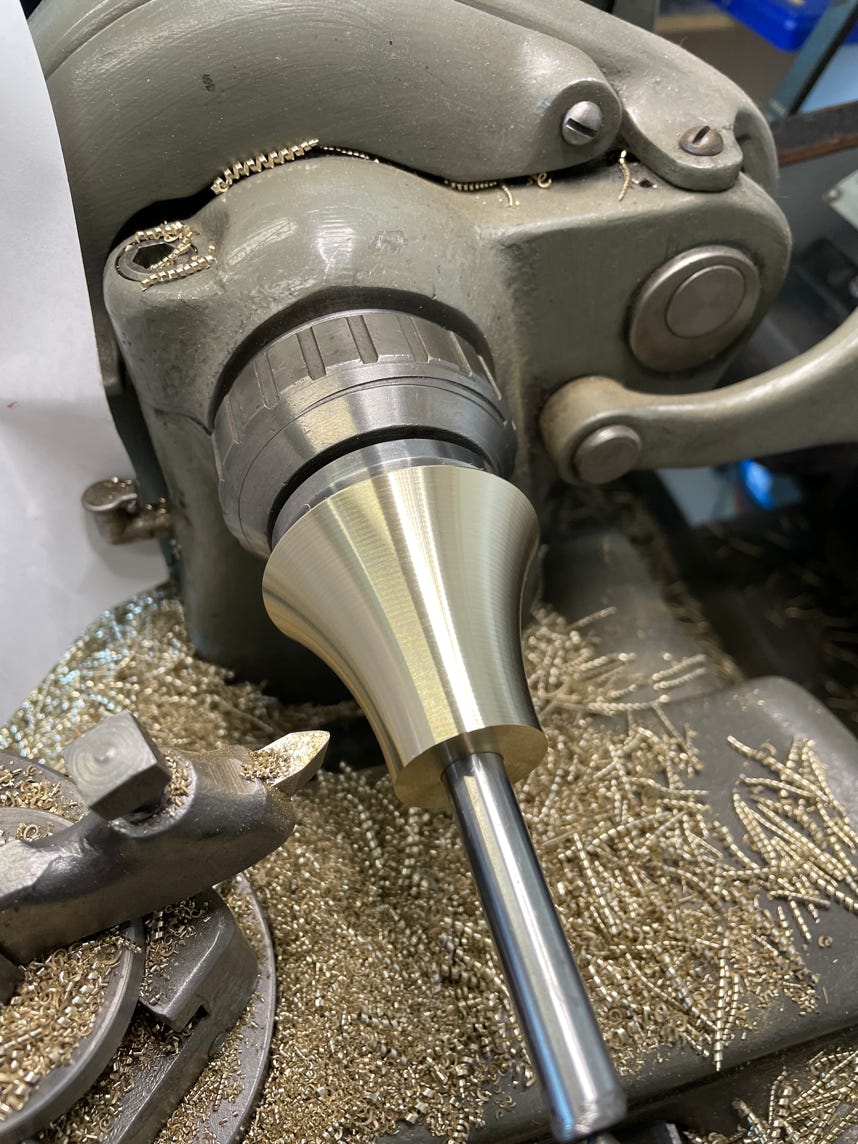
The blanks will be turned into cones.
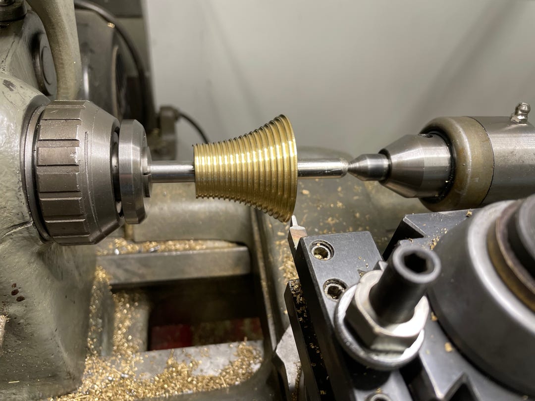
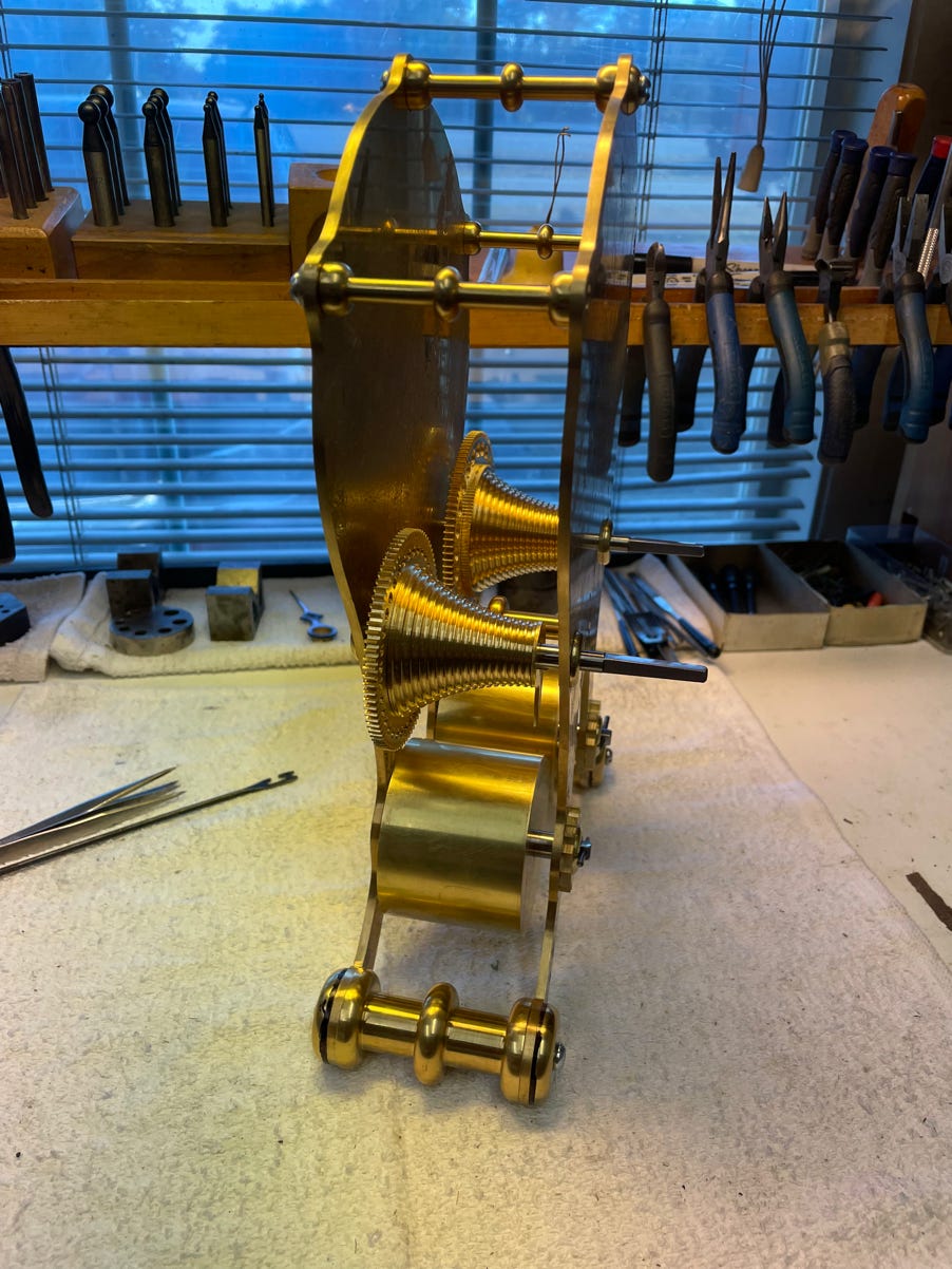
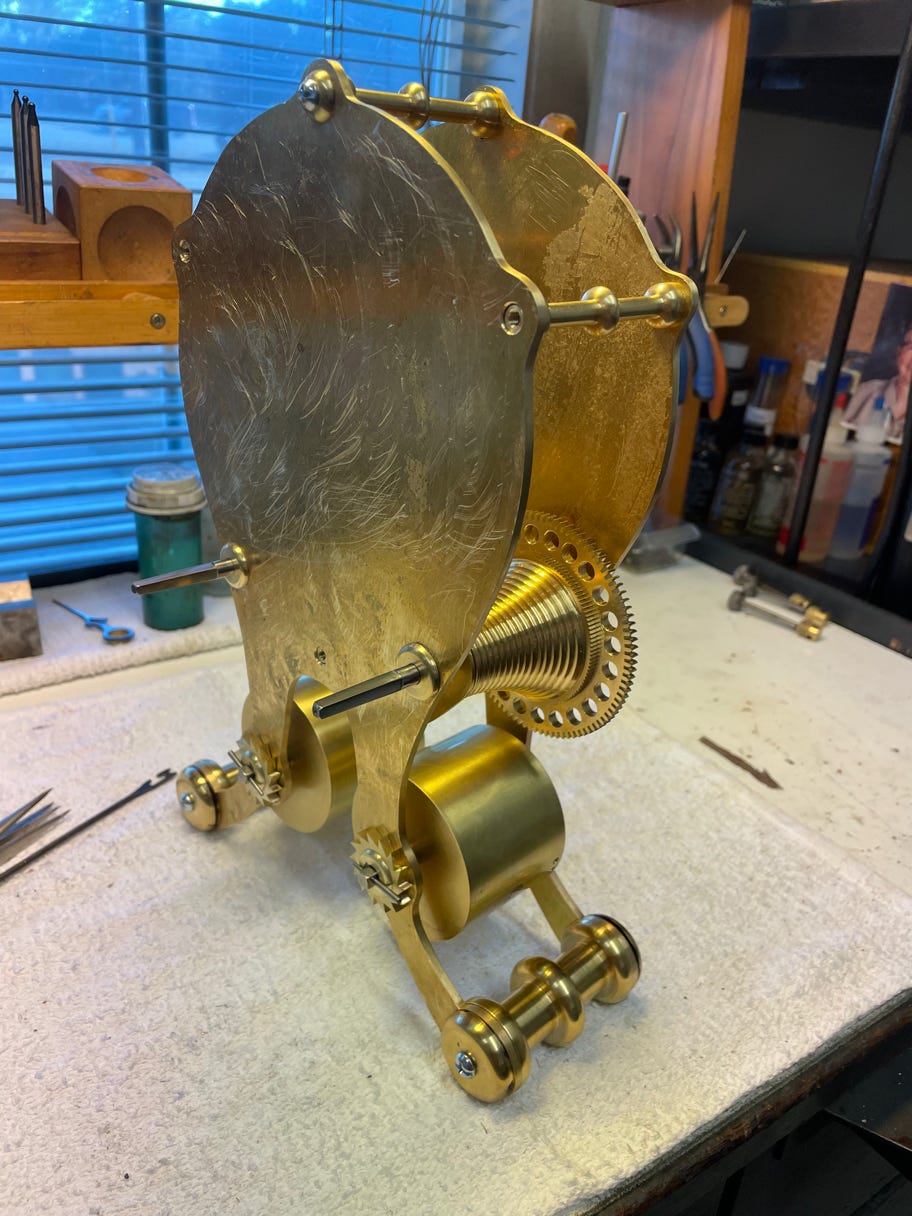
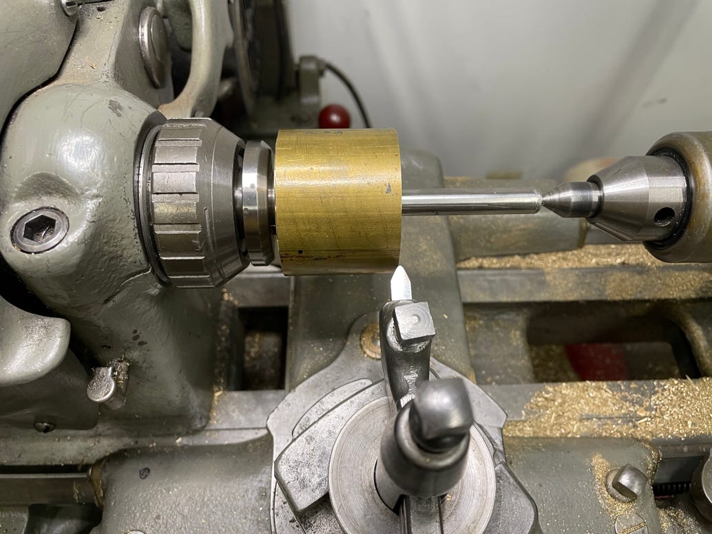
The threaded spiral is now cut into the cones. The spiral guides the cable or chain to wind the mainspring.

The fusee wheel blank is turned the proper diameter. I’m making three at the same time.
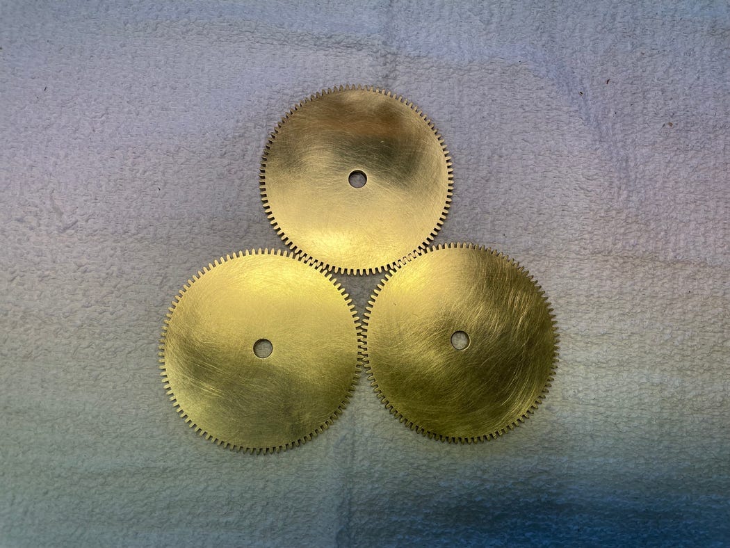
The teeth have been cut on the wheel blanks.

The fusee wheel has to have its true center restored before mounting it on an arbor.
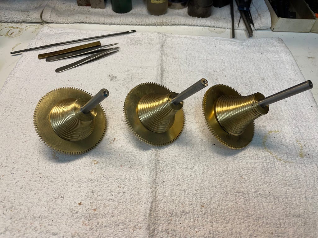
The fusee wheels are fit to the fusee arbors.
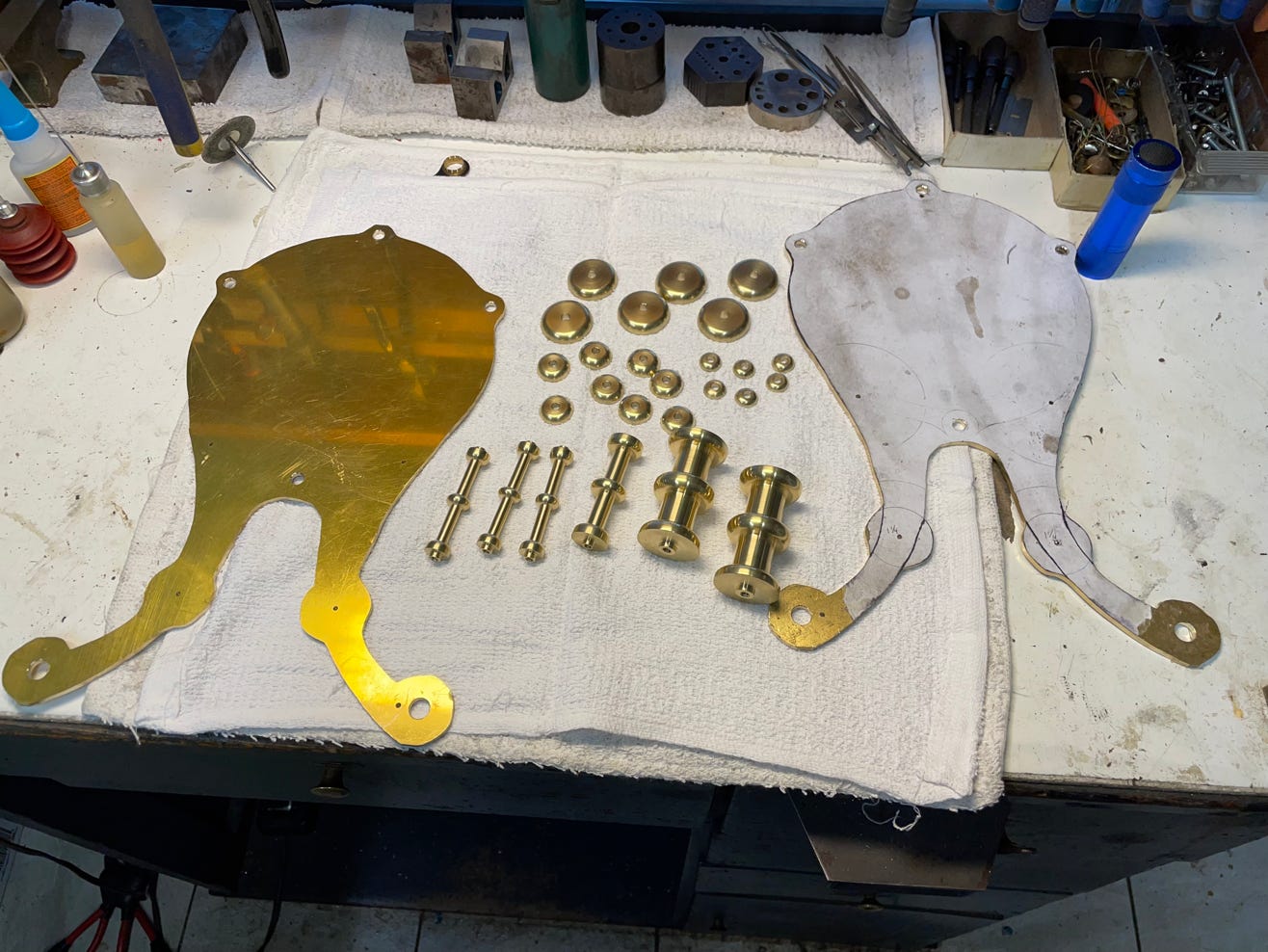
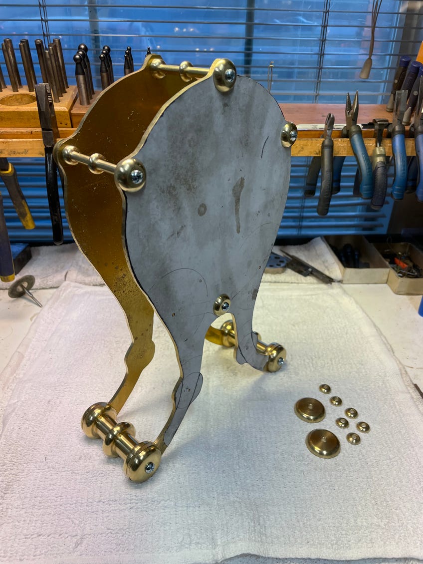
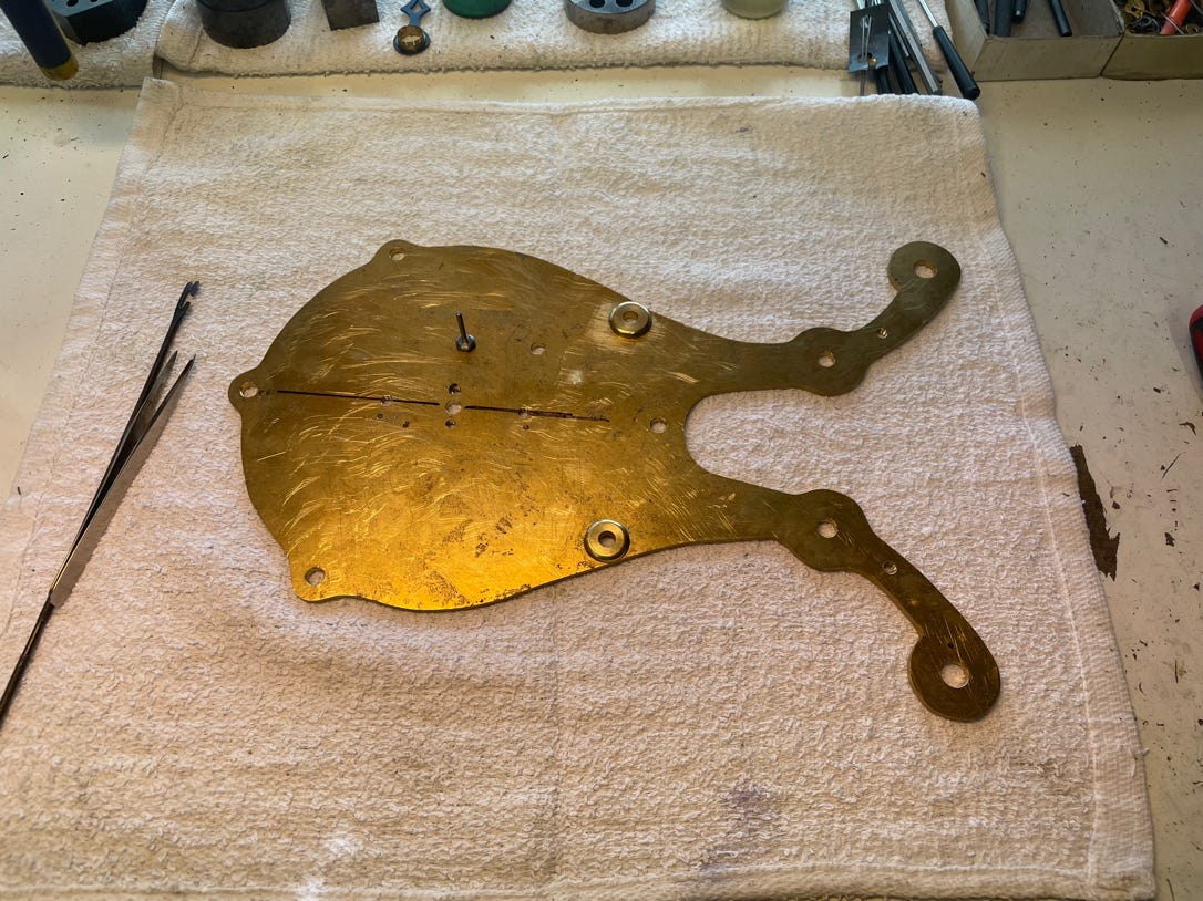
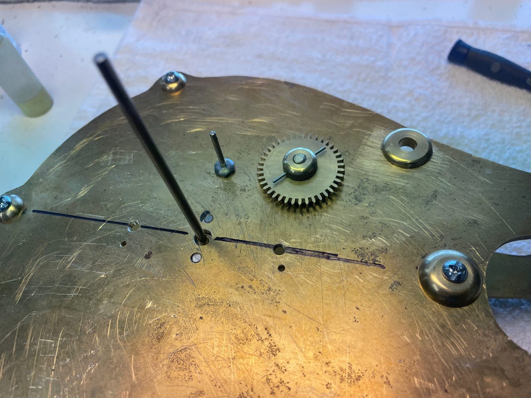
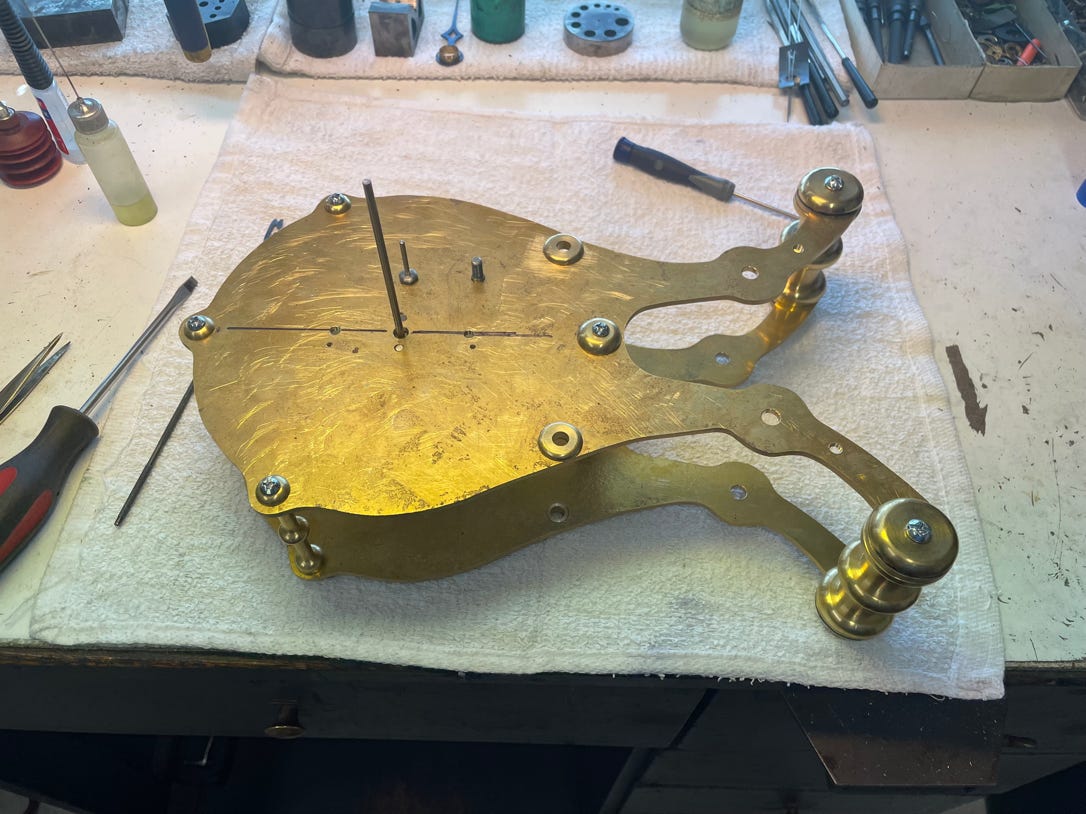
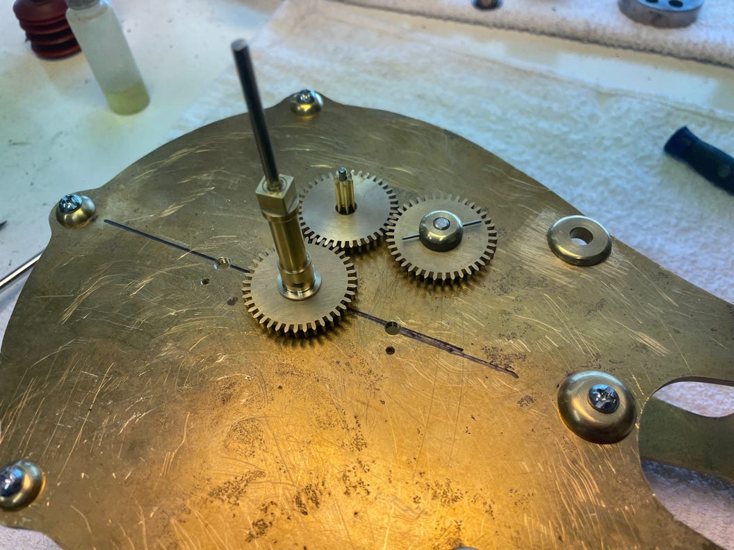
The clock is beginning to take shape! The overall design has been decided and the strike and time wheel trains have been calculated. These pix show the rough beginnings of the clock plates, pillars, and screw buttons. The clock design I decided on will be an 8-day, fusee driven, and hour striking (w/half hour passing strike) skeleton clock. It will incorporate a Coup Perdu (lost beat) deadbeat escapement with a large 60-tooth escape wheel. It will also utilize a center sweep seconds hand, which is unusual for a short shelf-type clock. Stay tuned. . .
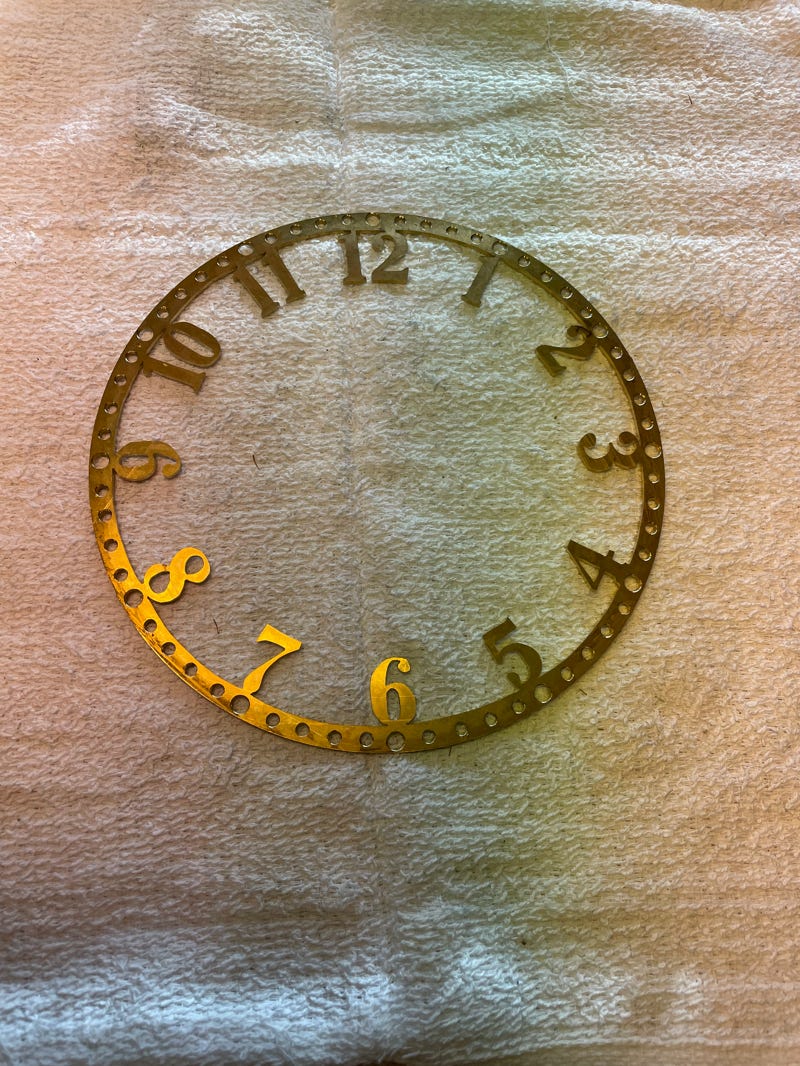
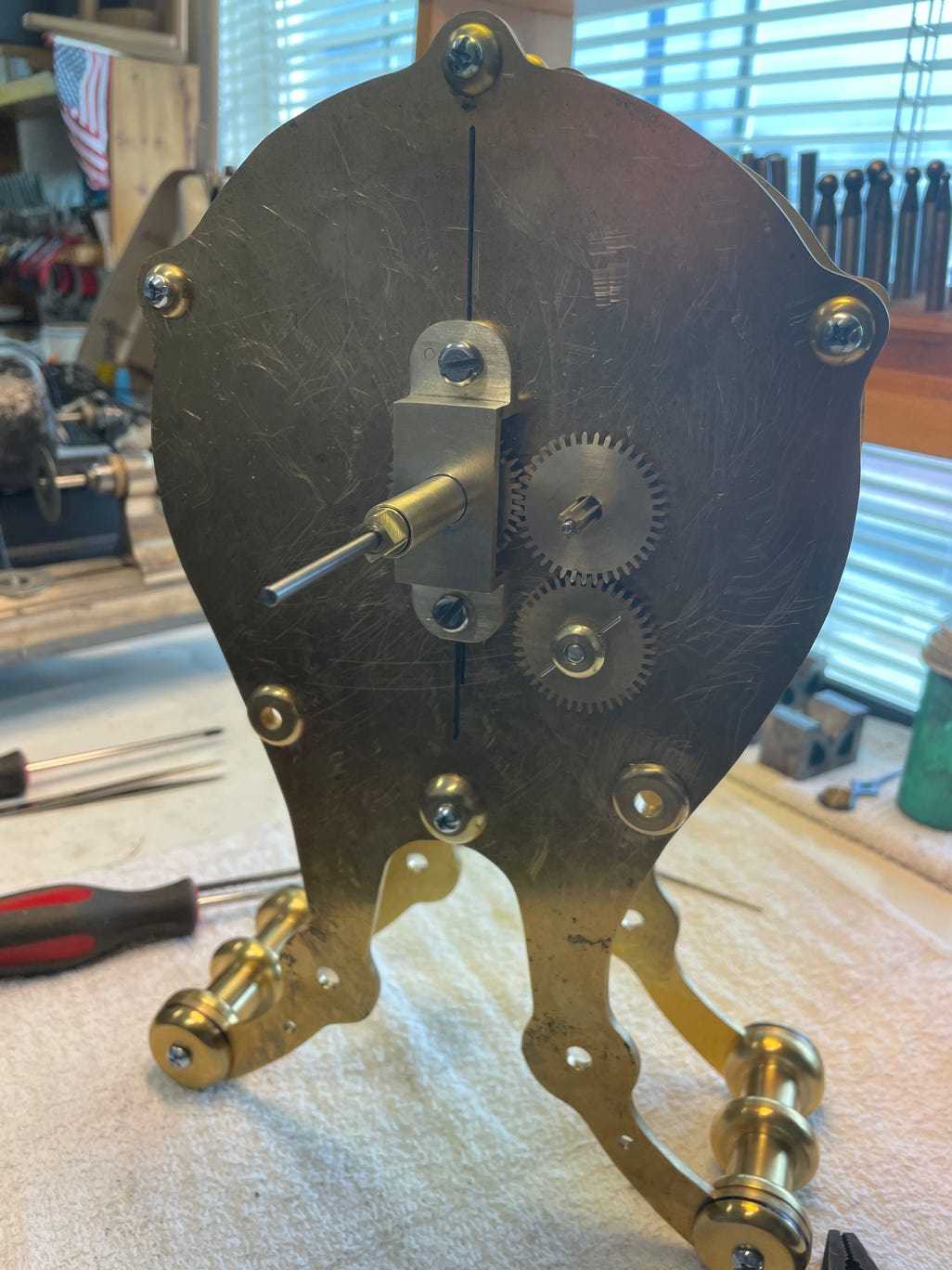
The clock dial has been “roughed out” and is the same diameter as the clock’s upper plates. Since this is a “skeleton” clock, most components will be minimal.
The clock dial has been “roughed out” and is the same diameter as the clock’s upper plates. Since this is a “skeleton” clock, most